VARK: High-Payload Robotic Wheel-Module Platform
Co-founder & lead engineer, sole engineer across mechanical, embedded, and software
- BLDC
- 3D-Printed Structure
- FEA
- AprilTag Localisation
- Motion Control
- Patent-Pending
TL;DR
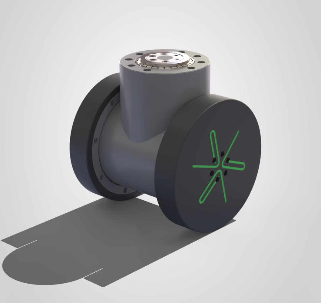
VARK is a high-payload robotic wheel module: attach modules to a passive structure (a trolley, a fixture, a platform that was never designed to move itself) and it becomes an AGV. Each module is rated to roughly 500 kg and works alone or in 2- and 4-module platforms. The structure is 3D-printed in PETG, FEA-validated, and designed from the start for local, low-cost manufacture rather than a conventional supply chain. The two halves of each module are identical by design, one component manufactured twice, which cuts both manufacturing difficulty and cost. The provisional patent covers both the wheel-module mechanism and the fleet coordination layer. In 2026 the platform was shortlisted for the Rolls-Royce Aerospace Open Innovation Challenge (modular engine handling for MRO); I authored the technical proposal, pitch deck, and video, and led direct engagement with Rolls-Royce engineering stakeholders. I own every layer: mechanical design, BLDC drive control, motion control, localisation, and the software above it.
The problem
Moving heavy, awkward things around industrial spaces usually means one of two bad options: buy a purpose-built AGV for every payload class, or keep pushing things by hand. Aerospace MRO makes the problem concrete: engine strip-down is fixed, sequential, and crane-dependent. A rigid disassembly order occupies 10–12 technicians for 2–3 weeks per engine, no parallel work is possible, and the facility layout dictates the workflow rather than the other way round.
VARK inverts the model: instead of buying a vehicle, you add drive modules to the structures you already have. The design targets that follow from that are cost, payload, and precision: a module cheap enough to deploy in numbers (the prototype-scale bill of materials is ~S$2,000 per unit, dominated by the printed structure, battery, and motors rather than any proprietary part), strong enough to take a ~500 kg share of a real industrial load, and accurate enough to position it.
System architecture
Each module is self contained: BLDC drive and motion control, a downward facing camera for AprilTag/QR-based localisation, and a 3D-printed structure, about 250 mm tall on 200 mm wheels. Differential drive lets a module turn on the spot and move laterally as part of a platform, with no changes to the floor or building. Modules are designed to operate fully independently or combine into 2- or 4-module platforms depending on the load (electromagnets assist alignment during docking and an electromechanical lock secures the joined platform), and combined platforms can work in coordination, then separate and operate in isolation again. Inter-module communication runs over Wi-Fi (in active development); the coordination approach is part of the provisional patent filing.
The drive module is one member of a family of "mobility building blocks": autonomy, actuator, sensing, and power modules that share the same mechanical and electrical interface, so a passive platform gets exactly the capability set its job needs, nothing more.
Key design decisions & trade-offs
Design decision
3D-printed PETG vs. machined metal
- Options considered
- Conventional machined or a 3D-printed PETG structure.
- What I chose
- 3D-printed PETG, FEA-validated to the 500 kg load case.
- Why
- The differentiator I'm proving isn't just the module. It's that a high-load AGV module can be manufactured locally, cheaply, and without dependency on external suppliers or specific countries. FEA showed minimal deflection at 500 kg in PETG, and the printed structure is what makes the ~S$2,000 unit cost possible with no tooling investment.
- What it cost me
- Lower stiffness headroom than metal. If a higher load capacity is needed, the design accepts aluminium strut reinforcement rather than a material change.
Design decision
One downward-facing camera vs. two 45°-angled cameras
- Options considered
- A pair of cameras angled at 45° for a wider view of the floor ahead, or a single camera looking straight down.
- What I chose
- Single downward-facing camera.
- Why
- Straight-down gives markedly better AprilTag/QR detection: consistent scale and minimal perspective distortion, which is what localisation accuracy actually depends on.
- What it cost me
- The chassis had to be widened to accommodate the camera placement, a real mechanical concession made for a sensing win.
Design decision
Wireless (Wi-Fi) inter-module comms vs. a wired bus
- Options considered
- A wired bus threaded through the host structure, or wireless links between modules.
- What I chose
- Wi-Fi between modules (in progress).
- Why
- The whole premise is attaching modules to passive structures that were never designed for them; requiring a wiring loom through the customer's trolley defeats the retrofit story.
- What it cost me
- Wireless coordination is the hardest part of the system and is still in active development; it's the current engineering front line, not a solved problem.
Testing & validation
The v1 drive unit is built and bench-proven: differential drive assembled with an 8:1 reduction delivering 39.6 N·m post-gearbox, turn-on-spot confirmed, AprilTag path planning and motion working, and the printed structure load-tested to 100 kg with structural integrity confirmed. The 500 kg per-module rating is FEA-validated: a static structural analysis of the wheel module under the 500 kg design load case shows a maximum total deformation around 0.2 mm. Carrying that load physically is what v2 is for, with a stronger printed structure and a staged load ladder (100 kg → 500 kg → module spec), FEA safety factor ≥2:1, and stability at 10° inclination as the exit criteria, on the way to the ≤10 mm docking-accuracy system spec.
Physical prototype testing is run with the unit chained to restrict travel, an emergency stop that cuts power to the entire system, and, in battery-powered operation, a wireless kill switch as the remote layer of protection.
The Rolls-Royce proposal
The Aerospace Open Innovation Challenge submission (Problem Statement 2, Modular Engine Handling, partnered with Rolls-Royce Singapore) forced the platform through the discipline of a real industrial requirements set, and the system architecture I proposed is scoped against it: 500 kg per-module load rating, multi-module platforms for engine-module frames from 500–2,000 kg, ≤10 mm docking accuracy, cradle changeover in under an hour, IEC 62443-aligned cybersecurity, and interlocked collision avoidance for mixed human-machine floors, across the Trent XWB-84k, 700, 1000, and 7000. The engine-mount platform design carries its own mechanisms: per-corner linear actuators give precision height adjustment for aligning engine modules during reassembly, and braking is fail-safe by geometry: all wheels retract into the frame so the rigid structure sits directly on the floor.
The proposal also covers the software layer, because an MRO operator buys a workflow, not a wheel: a builder interface to compose module configurations and map the facility (gates, routes, zones, task points), and a live digital thread: every engine module gets a unique ID, live location, timestamped movement history, and maintenance state, so the fleet produces audit-ready records as a side effect of moving things.
A full 12-module system, enough to move an engine's worth of module frames in parallel, comes in at an estimated S$65K including the engine mount platform, fail-safe braking, and software integration. That number is the point: it's a different order of magnitude from conventional engine-handling infrastructure, and it's achievable because every wheel module is the same S$2,000 unit built from commodity electronics and printed structure. The proposal was scoped as a phased de-risking plan (co-funded proof-of-concept, then a paid pilot with a 3+ unit fleet and full 3,500 kg load testing) rather than a promise of a finished product.
Results
- Provisional patent filed covering the wheel module and fleet coordination
- Shortlisted for the Rolls-Royce Aerospace Open Innovation Challenge 2026 (modular engine handling for MRO)
- Direct technical engagement with Rolls-Royce engineering stakeholders, off the back of a proposal, deck, and video I authored
- Working v1 prototype: 39.6 N·m per module, turn-on-spot, 100 kg load-tested; v2 (stronger structure, onboard localisation) in development
- Multi-module coordination in development
Failures & what I'd change
Safety
A ~500 kg-class drive module is dangerous by default, so test protocol treats it that way: the prototype is physically chained to restrict movement during trials, an emergency stop cuts power to the whole system, and battery-powered runs add a wireless kill switch so the unit can be dropped to safe-state without approaching it.