Q-Bot: 5-Axis Robotic Rendering & Material-Manipulation System
Installation technician → robotics engineer → design engineer, technical lead of the 5-axis system
- 5-Axis Motion
- Compliant Mechanisms
- Force Control
- Toolpath Generation
- Substrate Localisation
- Patent
- Certification
Publicly disclosed material only. The architecture described here is disclosed in Q-Bot's published patent WO2022208057A1, on which I am a named inventor, alongside publicly documented Q-Bot work. Client, site, and commercial detail that is not already public stays out.
TL;DR
Q-Bot is an award-winning built-environment robotics startup whose robots do the work humans shouldn't have to: confined, dirty, repetitive, and at height. Over seven years and three promotions I went from installing and operating robots on site to technical lead for a 5-axis robotic rendering machine: a research system built to replicate the entire external-wall-insulation rendering process (pneumatic pick-and-place of rock wool insulation sheets, spray render, smooth render, and surface finishing) through interchangeable, compliant tool heads. The architecture that came out of it is protected by a patent I am named on as co-inventor.
The problem
External wall insulation rendering is skilled, physically punishing work performed at height, and quality depends heavily on the individual applicator. The UK alone has nearly 8 million solid-wall homes; insulating those walls can cut heat loss by up to 40%, yet BRE research found many conventional installations failing within five years. The 5-axis machine was developed under a BEIS-funded innovation project (the Spray Applied Wall System), with Saint-Gobain Weber as materials partner. The research question behind it: can a robot execute the full process (placing insulation, applying render, smoothing, finishing) to a consistent standard on real substrates, where every wall is different and nothing is square?
System architecture
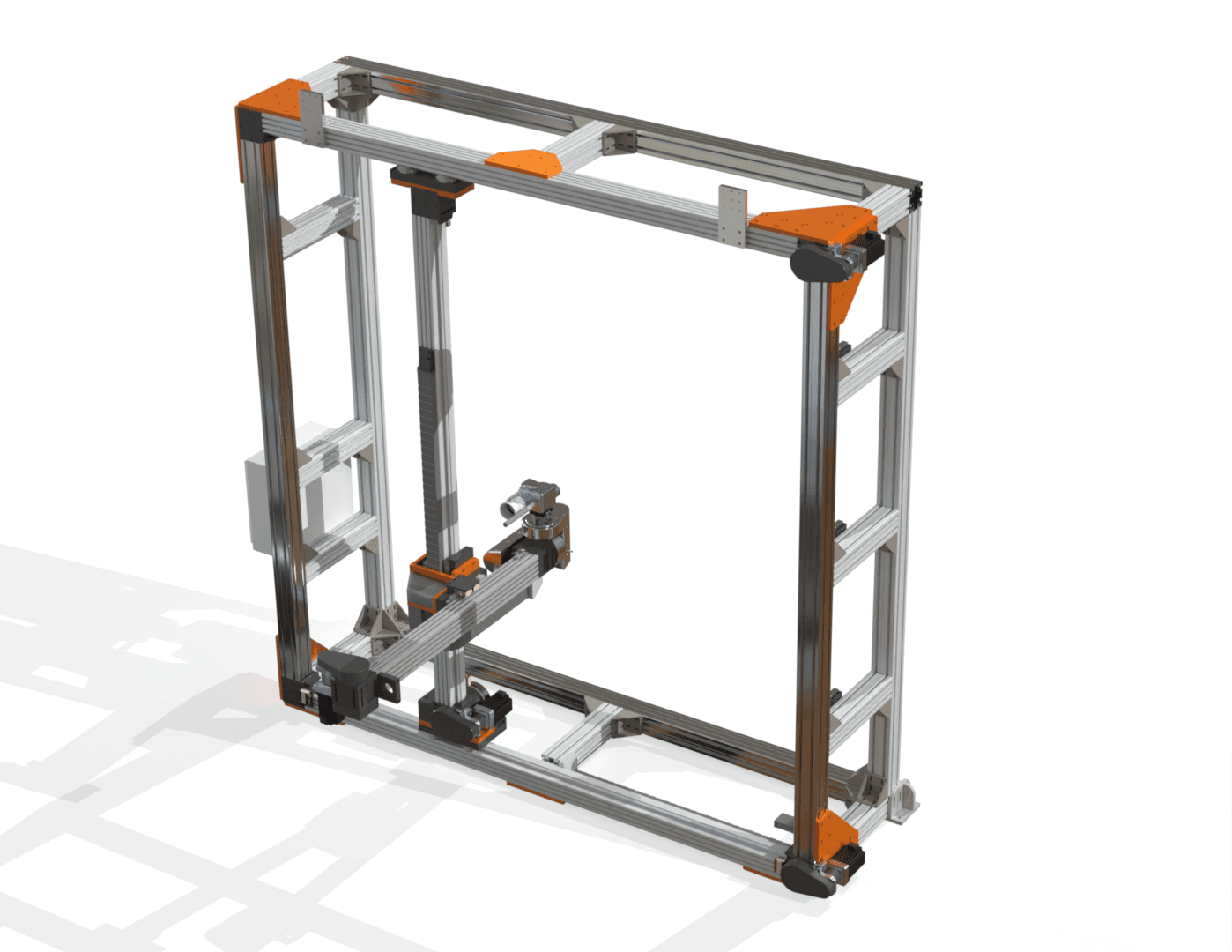
The pipeline: an onboard scanner detects the substrate's position and orientation → 3D tool paths are generated against the real surface → the 5-axis system executes them with the appropriate tool head. The motion platform is an XYZ gantry built on aluminium extrusion with belt-driven axes (chosen for speed and low moving mass), driven by BLDC motors through pulley reductions. The two rotary axes exist for a specific process reason: spray render wants the nozzle held perpendicular to the substrate, and real walls present compound angles, so the end effector carries two extra degrees of freedom rather than the gantry pretending walls are flat.
The tooling is interchangeable and compliant (wet-material spray nozzle, trowel, rotary scratching tool, probe, and a brick manipulator for replicating brick features) so one motion platform covers the whole process chain, from deposition through smoothing to finishing.
The accuracy problem
A robot can scan a wall and generate a toolpath, but a real building is not geometrically perfect and the scan is not accurate enough to run a rigid finishing tool against it blindly. Depth sensing of this class resolves to roughly ±5 to 25 mm. A nominally flat 6 m wall varying by 1% can deviate by around ±60 mm. The render layer itself is only about 15 mm thick. Follow the scanned geometry alone and the tool either misses the render entirely or digs straight through it.
The answer is two layers of position control: coarse geometric control from the scan and the gantry, and fine mechanical compliance with feedback at the tool.
The compliant tool head
Rather than bolting the trowel rigidly to the machine, we built a compliance module between the arm and the tool: a spring-loaded linear rail with a linear encoder on it. The spring pushes the tool toward the wall, the wall pushes back and drives the carriage along its stroke, and the encoder measures exactly how far it moved. The robot no longer needs to know the wall's position to sub-millimetre accuracy, because the mechanism physically absorbs the error the scan could not resolve.
The encoder is what turns passive springiness into control. For a spring of known rate, force follows displacement: F = kx. Measuring compression gives an estimate of the contact force the tool is applying to wet render, so the machine can hold a target force while moving across an imperfect surface, which is roughly what a plasterer does by feel. It gets there without a six-axis force/torque sensor at the wrist, which would have cost more than the rest of the head. The same displacement signal feeds back into the trajectory: if the surface sits consistently closer or further than expected, stand-off and toolpath can be corrected as the machine works.
The principle extends to the other tools through a different signal entirely. On the rotary scratching tool, driven by a BLDC motor, motor current is a proxy for how hard the tool is biting into partially cured render, so contact depth can be inferred and corrected without adding a sensor at all.
Key design decisions & trade-offs
Design decision
6-DOF robotic arm vs. 5-axis system on linear rails
- Options considered
- The project began as a 6-DOF robotic arm concept, versus a simplified 5-axis architecture built around linear rails.
- What I chose
- 5-axis with linear rails.
- Why
- Off-the-shelf arms forced a bad triangle: human-safe with high payload but too expensive, human-safe and affordable but weak, or strong and affordable but unsafe to work around. Dropping a degree of freedom and moving to rails broke the triangle (higher payload, easier control, and human-safe operation) because rendering doesn't need an arm's dexterity, it needs stiffness and repeatability across a large workspace.
- What it cost me
- Less kinematic flexibility than an arm; the machine is committed to the class of surface it was designed for.
Design decision
Custom path planner vs. repurposed 3D-printing toolchain
- Options considered
- Write a bespoke path-planning stack for render deposition, or drive the machine with G-code generated by slicing software built for 3D printers.
- What I chose
- Slicer-generated G-code through a universal G-code sender.
- Why
- Render deposition is layered material extrusion over a surface, structurally the same problem a 3D-printer slicer already solves. Repurposing the slicing toolchain, with parameters tuned to mimic how a human sprays, got the machine executing real toolpaths without spending the project on motion-planning software.
- What it cost me
- The toolchain thinks in printer conventions, so process-specific behaviour has to be expressed through slicer parameters rather than owned code. Fine for a research prototype, a real constraint for a product.
Testing & validation
Every axis was proven in isolation before assembly. The linear-axis drivetrain (BLDC motor through a pulley reduction) was sized by calculation to roughly a 3× force margin over the worst-case payload, then validated on a purpose-built rig, lifting 20 kg vertically at 0.5 m/s. After the full machine was assembled horizontally and hoisted vertical, the vertical axis was measured lifting 60 kg at 0.25 m/s. The rotary axes were specified from the worst-case tool (spray nozzle with a loaded hose): enough torque to swing 90° in under a second, with sealing to survive wet render.
The machine then ran the tests that matter: dry runs executing generated toolpaths against a real wall, followed by spray trials with Weber render, extruding material in layers, 3D-printer style, onto vertical substrate. Getting the render consistency right proved harder than the motion.
The prototype was also designed against an industrial specification rather than lab standards: mission-life and MTBF targets, 20 g shock resistance, and design practices aligned to the LVD, EMC, and Machinery Directives with RoHS-compliant material selection, plus full part numbering and revision control. A research machine, engineered like a product.
The certification story
Hardware only counts when someone signs it off. I personally carried out and passed BBA certification testing (British Board of Agrément) for Q-Bot's underfloor insulation system, designing and running the test process that turned an internal capability into a certified, quality-assured method the whole company could deploy against. I also designed the pneumatic high-pressure polyurethane spray tooling used for insulation application. To be precise about scope: the BBA certification applies to the underfloor insulation product, not to the 5-axis rendering machine, which was a research prototype. That work is why I treat test rigor as a design discipline rather than a final gate: the certification requirements fed directly back into the tooling design.
Field engineering
The robots earned their keep in real buildings, which meant somebody had to keep them alive out there. I diagnosed and rebuilt robotic modules in the field, designed the test rigs and jigs used to verify them, and machined precision replacement parts to improve equipment reliability. The unglamorous work that separates a demo robot from a deployed one.
The software around the machine
The 5-axis machine didn't work alone; its render was fed by a separate supply machine, and I built the production app that controlled it: a cross-platform Flutter tablet app, connected over Bluetooth, with a visual display of every component's state machine and its live state. An operator could see at a glance exactly which state each part of the supply system was in, rather than inferring it from behaviour. Building the software that operators actually used, not just the robot, is a big part of why I think in whole systems.
Results
- Promoted three times in seven years: installation technician → robotics engineer → design engineer, ending as technical lead of the 5-axis system
- Named co-inventor on WO2022208057A1, filed March 2021 and granted in the UK as GB2605372B in 2024, covering the sensorised compliant tool head and the control method behind it
- BBA certification personally carried out and passed for the underfloor insulation system, enabling company-wide quality assurance (the 5-axis rendering machine itself was a research prototype, not a certified product)
- Full rendering process chain (pick-and-place, spray, smooth, finish) demonstrated on one robotic platform, including spray trials extruding real render onto vertical substrate
- Axis-level validation passed: ~3× calculated force margin confirmed on a test rig (20 kg at 0.5 m/s), 60 kg measured lift on the assembled vertical axis
The patent
The compliance architecture is protected by WO2022208057A1, filed in March 2021 and granted in the UK as GB2605372B in 2024, on which I am a named co-inventor. The granted claim is specific about the mechanism described above: a compliant tool head with a biasing mechanism, a sensor detecting tool displacement, a controller that adjusts the toolpath from that displacement, and an actuator that moves the compliance module accordingly. Hardware architecture and control method both.
To be clear about scope, the filing also covers embodiments that were never built as hardware, including insulation pick-and-place and a mobile gantry for scaling facades. What this page describes as built is what existed as built.
Failures & what I'd change
The biggest design lesson is baked into the architecture section above: the project's original 6-DOF arm concept had to be abandoned for complexity and payload reasons. Committing earlier to "the simplest kinematics that do the job" would have saved a development cycle, a lesson I've applied to every machine since.
Safety
The 5-axis system operated in a dedicated, barricaded cell with safety switches and stops throughout; a machine moving 50 kg tooling through large sweeps is treated as an industrial cell, not a lab bench.